eddyfi Ectane 2
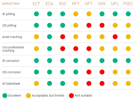
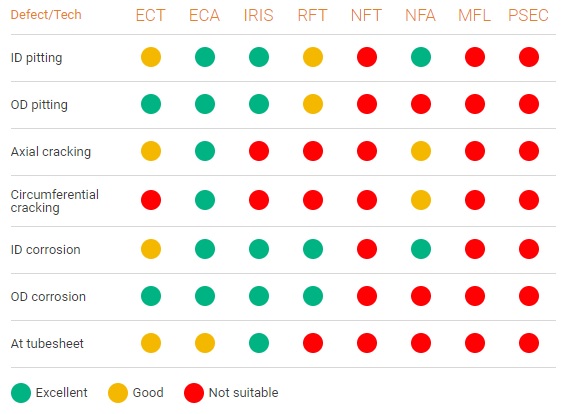
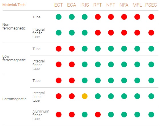
Non-destructive testing of tubing and surfaces relies on a number of techniques, which often depend on the application and the materials involved. Use the Ectane 2 ‘s built-in capabilities with almost any combination of the following testing technologies, according to your needs.
Eddy current testing is a non-contact method used to inspect non-ferromagnetic tubing. This technique is the fastest and most reliable tube inspection technique.
Theory of operation
In its most basic form — the single-element eddy current testing probe — a copper wire is excited with an alternating electrical current. This wire produces a magnetic field around itself in the direction ascertained by the right-hand rule. This magnetic field oscillates at the same frequency as the current running through the coil. When the coil approaches a conductive material, currents opposed to the ones in the coil are induced in the material — eddy currents.
A defect in the conductive material disturbs the path of eddy currents, creating a local magnetic field that changes the balance of the system. This can be detected by measuring the changes in impedance in the coil, which is a telltale sign of the presence of defects.
Applicable tube material
- Non-ferromagnetic materials like Brass, Copper, Copper-Nickel, Stainless steel, Brass, Inconel, hastalloy and slightly magnetic alloys like Monel 400.
- Can inspect tubing that has been coated with non-conductive coating.
Benefits
Several benefits are derived from eddy current testing:
- It is suited to volumetric flaws such as corrosion, wear, and large porosities, as well as cracking.
- It can detect surface-breaking, near-surface, and far-surface defects.
- ECT probes don’t need to be in contact with the part under inspection.
- Eddy current testing can be used in applications other than flaw detection.
- Parts under test require only minimal preparation.
Eddy current testing is a non-contact method used to inspect non-ferromagnetic tubing. This technique is the fastest and most reliable tube inspection technique.
Theory of operation
An eddy current array, in its simplest form, is a series of single elements arranged in a row, allowing users to cover a larger area in a single pass than conventional, single-coil probes (i.e., pencil probes using ECT). However, this could lead to sub-optimal results. That’s why ECA probes use multiplexing.
Multiplexing involves activating and deactivating coils in specific sequences to leverage the probe’s width. Multiplexing also minimizes the interference between coilsin close proximity (mutual inductance) and maximizes the resolution of the probe.
ECA probes effectively eliminate the raster scanning necessary when using ECT pencil probes. This has a significant impact on inspection speeds.
Benefits
ECA is a major improvement over single-element ECT because:
- Faster inspections
- Wider coverage
- Less operator dependent — eddy current array probes yield more consistent resultscompared to manual raster scans
- Better detection capabilities
- Easier analysis because of simpler scan patterns
- Improved positioning and sizing because of encoded data
- Eddy current array probes can easily be designed to be flexible or shaped to specifications, making hard-to-reach areas easier to inspect
Tangential eddy current array (TECA) is an advanced electromagnetic inspection technology that uses ECA to introduce alternating currents into the surface of the component under test to detect and size surface breaking cracks.
Just as with other eddy current techniques, cracks disturb the eddy current field generated by TECA and the return signal is instantaneously detected and sized. Probe operators are alerted on the spot of the presence of defects and their gravity. TECA also benefits from data recording and report generation, which are major advantages over alternative NDT methods.
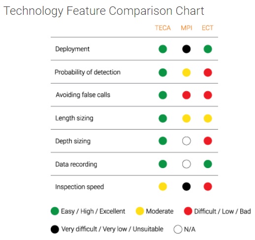
Results from independent testing show that TECA exhibits better overall performances than magnetic particle testing (MT). TECA’s probability of detection (PoD) is significantly higher and the probability of making false calls much lower.
Theory of operation
TECA is the perfect blend of multiplexed tangential coils and pancake coils. This advanced topology eliminates the need for multiple or raster scans, as it allows scanning wide surfaces in a single pass, which drastically reduces the time necessary to perform inspections. Tangential coils are positioned on their sides, their central axes parallel to the surface. The word tangential hints at the fact that eddy currents flow parallel to the surface and “dive” under cracks to measure their depth.
The Sharck probe is the current embodiment of TECA, applied to carbon steel welds.
While tangential eddy current is not an entirely new concept, it has never before been used in an array technique with high performance multiplexing. One of TECA’s key advantages is that it offers signals similar to traditional ECT pencil probe signals, making TECA easy to learn, minimizing the ramp-up time, while being a more information-rich technique.
Remote field testing (RFT) is being used to successfully inspect ferromagnetic tubing such as carbon steel or ferritic stainless steel. This technology offers good sensitivity when detecting and measuring volumetric defects.
Theory of operation
RFT probes use one or several transmitter coils positioned two tube diameters apart from the receiver coil. The magnetic field created by the transmitter coil travels through and out of the tube wall, radially and axially, towards the receiver. The magnetic field must travel through the tube wall again to reach the receiver. This is called through-transmission and is what defines RFT. Through-transmission allows external and internal defects to be detected with equal sensitivity.
Two coupling paths exist between the transmitters and receivers. The direct path, inside the tube, is rapidly attenuated by circumferential eddy currents induced in the tube’s wall. The indirect coupling path originates in the transmitter’s magnetic field that diffuses radially outward through the wall. At the outer wall, the field spreads rapidly along the tube with little attenuation and rediffuse back through the pipe wall and are the dominant field inside the tube at the receiver. Anomalies anywhere in the indirect path cause changes in the magnitude and phase of the received signal, and can therefore be used to detect defects.
Benefits
RFT has several benefits over other electromagnetic testing techniques:
- Suitable for ferromagnetic materials
- Equal sensitivity at the inner and outer surfaces
- Highly sensitive to wall thickness variations
- Can be used with less fill factors than ECT
Near field testing (NFT) technology is a rapid solution intended specifically for fin-fan carbon-steel tubing inspection.
Theory of operation
NFT technology uses two coils — a transmitter and a receiver. Typically the receiver coil is close to the transmitter coil, taking advantage of the transmitter’s near-field zone — that is, the zone where the magnetic field from the transmitter coil induces strong eddy currents, axially and radially, in the tube wall.
NFT probes operate within the same frequency range as remote-field testing (RFT)probes.
NFT is specifically suited to detecting corrosion, erosion, and pitting inside carbon steel tubing. NFT is perfect for fin-fan tube heat exchangers because eddy currents do not go through the wall of the tube. NFT is also much more sensitive to defects close to structures such as support plates and tube sheets.
Benefits
- Fast
- No need for an external reference coil
- Easy to use
- Unaffected by structures such as support plates and tube sheets
Near-field array (NFA) is the multiplexed evolution of near-field testing (NFT). Thanks to its sizing capabilities, it is an excellent alternative to IRIS in fin-fan air coolers and ferromagnetic heat exchanger tubing.
Theory of operation
By design, aluminum-finned carbon steel tubes are one of the most challenging tubular components to inspect. The external aluminum fins of these tubes greatly influence the quality of inspection signals making it difficult to size pitting, cracking at the tubesheet, tapering, and general wall loss in such tubes. Obviously, because the magnetic field of remote-field testing (RFT) propagates through and outside the tube wall, the technique cannot be used in aluminum-finned tubes. However, inspection companies use other techniques (NFT, magnetic flux leakage (MFL), partial saturation eddy current testing (PSEC), internal rotary inspection system (IRIS)) that do not have this limitation.
NFA technology functions in transmit-receive mode. A single bobbin coil acts as the transmitter to generate the near field, an absolute bobbin receiver coil detects and sizes the general internal wall loss, and up to two rows of multiplexed receiver coils cover the entire inner surface of aluminum-finned tubes (full 360°). With up to 30 optimized coils and thanks to channel multiplexing, NFA is capable of generating high-quality signals yielding a very good signal-to-noise ratio (SNR) that allow detecting circumferential and axial cracking. The coil configuration of NFA also enables C-scan imaging despite a scan speed equivalent to NFT at 300 mm/s (12 in/s) in tubes ranging from 19.1 mm to 38.1 mm (0.75–1.50 in) in diameter. So doing, NFA technology gives probes the necessary resolution to reliably detect and size small, volumetric defects approximately 3.2 mm (1/8 in) in a single pass.
Compared to other inspection technologies, near-field array technology is easier to deploy. NFA does not incorporate any magnets, so probes are easy to push and pull through tubes, and are not as sensitive to pull speed as MFL probes. NFA probes also do not require water or complex tools, making them much easier to use than IRIS.
Benefits
- Inspect air cooler tube with a high-resolution array, providing intuitive C-scans at NFT speeds
- Detecting and sizing internal defects in one pass
- Detecting axial and circumferential cracks
- Easy to use (no magnet = easy to push and pull)
Magnetic flux leakage (MFL) is a fast inspection technique, suitable for measuring wall loss and detecting sharp defects such as pitting, grooving, and circumferential cracks. MFL is effective for aluminum-finned carbon steel tubes, because the magnetic field is almost completely unaffected by the presence of such fins.
Theory of operation
MFL uses a powerful magnet to magnetize the conductive material under test (usually steel). Where there are defects — corrosion or material loss — the magnetic field “leaks” from the steel.
MFL probes incorporate a magnetic detector placed between the poles of the magnet where it can detect the leakage field. During inspection, a magnetic circuit of sorts forms between the part and the probe. The magnetic field induced in the part saturates it until it can no longer hold any more flux. The flux overflows and leaks out of the pipe wall and strategically placed sensors can accurately measure the three-dimensional vector of the leakage field.
Because magnetic flux leakage is a vector and that a sensor can only measure one direction, any given probe must have three sensors to accurately measure the axial, radial, and circumferential components of an MFL signal.
Benefits
Using MFL can yield the following benefits:
- One of the few methods used to inspect finned tubes (NFT is also an alternative)
- Can be used on all ferromagnetic materials
- Good sensitivity to pitting
- High-speed inspection
The internal rotary inspection system (IRIS) is an ultrasonic non-destructive testing (NDT) technique used to inspect pipes and tubes.
Theory of operation
Because IRIS is an ultrasonic technique, it requires a couplant. In this case, water. Tubes under test must therefore first be flooded to use this technique. IRIS relies on a transducer to generate an ultrasonic pulse parallel to the axis of the tube under test. It also relies on a rotating mirror that directs the ultrasonic wave into the tube wall. The mirror is driven by a small turbine powered by the pressure of water pumped into the tube.
Part of the ultrasonic wave is reflected by the inner-diameter (ID) wall, while the rest is reflected by the outer-diameter (OD) wall of the tube. Because the ultrasonic velocity of the tube’s material is known, it is possible to assess the thickness of the wall by calculating the difference in times of flight between the two diameters.
As the probe is pulled, the spinning motion of the mirror results in a helical scan path.
A critical aspect of IRIS is ensuring that the mirror is at the center of the tube. An off-center ultrasonic pulse yields a distorted scan image because of the different ID and OD wall sound paths. That’s why our IRIS kits are equipped with centering deviceshelping operators keep the system centered.
IRIS is commonly used in boilers, shell-and-tube heat exchangers, and fin-fan heat exchanger tubes.
